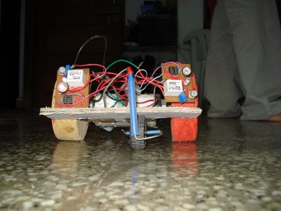

This is my second autonomous robot project. Well this robot is a bit different from the line racing one, in this robot the robot sends pulsating infrared beam which in turn reflects from a object and is detected by a photo diode .the robot is using a differential drive system. I have used two such sensors one on the left and one on the right .the right sensor controls the left motor and left sensor controls the right motor.When both the sensors are not sensing any object both the motor runs in a strait line ,when the right sensor senses the object it stops the left motor thus turning it towards left and same for the left sensor this is well explained in the following figure...
This circuit is quite simple; IC 555 in astable mode is used to produce a pulsating infrared beam and a receiver circuit is used to detect it.....

TRASMITTER:
Well the time period of the circuit can be calculated using the formula T=0.693*(R(1)+2*R(2))*cWhere T is the time period and you can get frequency=(t)^(-1).you can also directly connect the terminals of the IR diode to the 5 volts supply and use it as transmitter ,tadaaa but here is a problem the IR diode takes nearly 0.2 Amp quite thirsty isn't it its simply wasting of batteries and the heat generated in the IR diode Is also quire large I*I*R so in order to overcome these defaults I have used IC 555 (timer) and reduced its duty cycle nearly to 30 percent thus saving my batteries. I have set the time period of the pulse in the range of Kilo hertz don’t set your time period in Mega hertz the IC wont respond and will not work.the following is the circuit diagram.
RECIEVER:
This is quite simple ,The IR photo diode detector the IR signal and feeds it to the transistor which in turn switches the relay
- The detector also switches in sunlight and ambient stray light .to fix this problem I have used a photographic camera film it allows only IR light to pass through it sounds ugly but it works and thus acts as a filter.
- The pulsating light also produce a pulsating signal at the emitter and thus the relay cant switch ,thus to screw itI have used a capacitor in parallel with the relay thus converting the signal from pulsating the DC.

And now the circuit works.....here is the amended circuit diagram.
testing .........testing.............
Wake up guys now how will you strain your thinkbox
You might be frustating how do I test my emitter and receiver individually ,we can't see infrared then how do I test it sounds tricky isn’t it !!!!!!!!well don’t panic its quite simple for testing your IR emitter there are two ways
1>Connect a simple LED in parallel with the IR diode ,if it glows its working .
2>This method is quite simple if you have an digital camera ,camcorder ,web cam, mobile cameras............etcthen view it through your cam screen your emitter IR led glows as shown it appears a bit violet in the screen,for instance you can also view your TV remote with any button pressed.
This is how it appears when you capture it
testing your receiver
1>place the TV remote in front of the photo diode this should switch the relay.
2>or else detach the photographic film and expose the diode to a bright light source this should switch the relay.
excited !!!!!!!!!!!!!!
but this circuit has some limitations
1>If used out doors the sunlight interferes .
2>The detector is not so sensitive as opamp circuit.
3>The circuit cannot detect black objects .
4>Its in inefficient against small obstacles .
5>Cross fade occurs if the surfaces are very reflective.


